Bathroom plumbing is one of the more tightly regulated systems in residential construction, with specific rough-in dimensions for every fixture and clear drainage and venting requirements that must be met before walls close. A bathroom plumbing diagram gives you a visual reference that coordinates supply lines, drain lines, and vent pipes before the first hole is cut. A bathroom plumbing rough in diagram shows where each fixture drain and supply stub-out must land relative to walls and floor, and these measurements must be precise or the fixtures will not align at installation. A bathroom plumbing layout drawing that shows both plan view and elevation helps you identify conflicts between pipes and structural members before they become expensive field problems. Creating a plumbing diagram for bathroom projects before rough-in day saves rework and keeps your inspection on schedule.
This guide covers the key rough-in dimensions for common bathroom fixtures, how to read and create a bathroom layout drawing, and the venting rules you cannot skip.
Standard rough-in dimensions for bathroom fixtures
Toilet rough-in
The standard toilet rough-in distance is 12 inches from the finished wall to the center of the drain. Some older toilets use a 10-inch or 14-inch rough-in; always verify the toilet specification before setting the flange. The bathroom plumbing rough in diagram must place the toilet flange 15 inches minimum from any side wall and 15 inches from any fixture or obstruction, measured center to center. NEC and local plumbing codes may require 18 inches from center to any side wall for ADA-accessible bathrooms.
Lavatory sink rough-in
A standard lavatory drain stub-out sits 18 to 20 inches off the finished floor for most pedestal sinks. Wall-hung vanity styles place the drain at 24 to 26 inches. Hot and cold supply valves land at the same height as the drain, 8 inches apart center to center for most single-hole faucets. Your bathroom plumbing layout drawing should show these dimensions for each sink individually because vanity heights vary by product.
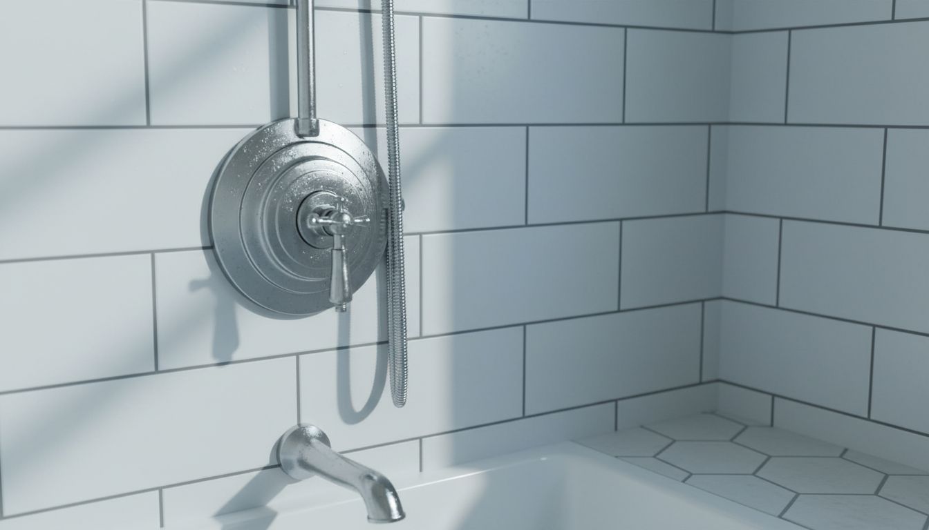
Shower and tub rough-in
Shower drain centers land at the geometric center of the shower base or the position specified by the pan manufacturer. The hot supply stub-out for a shower valve sits approximately 42 inches off the finished floor for a standard mixing valve; the cold stub-out is on the opposite side, also at 42 inches. A bathroom plumbing diagram for a shower-tub combination must show the overflow drain location, the tub spout stub-out height, and the showerhead stub-out at approximately 72 to 80 inches.
Venting requirements in bathroom plumbing
Every fixture trap requires a vent to prevent siphoning. The plumbing diagram for bathroom vent runs must show each vent pipe rising to connect to a vent stack or running individually through the roof. Wet venting is permitted in many jurisdictions for bathroom groups where the lavatory drain also serves as the vent for the toilet. This arrangement reduces the number of roof penetrations required. Check your local code adoption of the IPC or UPC to confirm which wet venting configurations are permitted before finalizing your bathroom plumbing layout drawing.
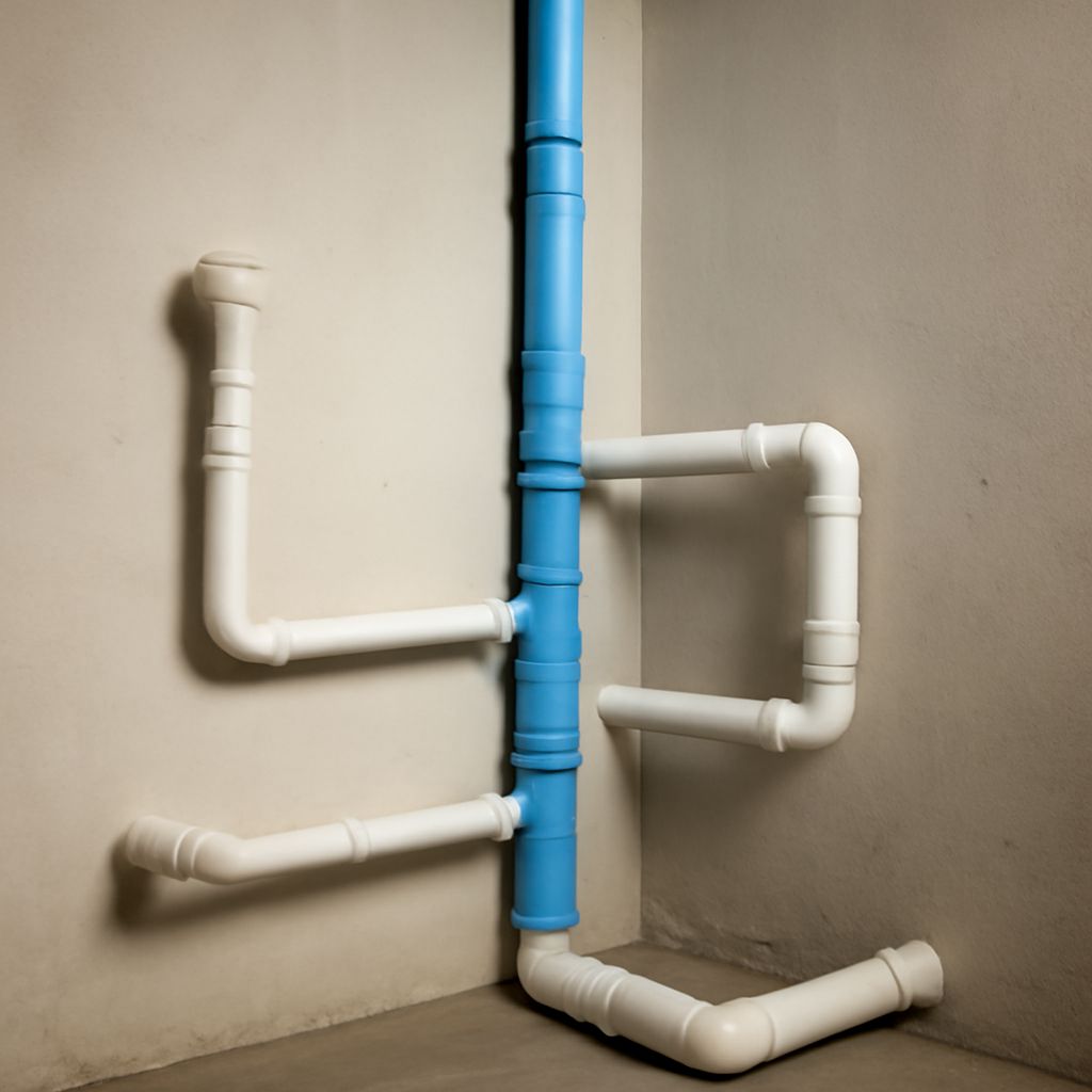
How to create a bathroom plumbing diagram
Start with a plan view of the bathroom at a consistent scale. Mark each fixture’s drain location, supply stubout positions, and vent chase locations. Note the floor joist direction, since drains must slope 1/4 inch per foot toward the main stack and must run between or below joists. Add an elevation view for shower walls showing valve heights and showerhead positions. A complete bathroom plumbing rough in diagram includes the sewer connection point, the vent termination elevation, and the main shutoff valve location. Keep this drawing on file for every future plumbing repair or renovation.