Plumbing Blueprints: How to Read and Create Residential Plans
Plumbing blueprints are the technical drawings that show where every supply line, drain, vent, and fixture connects in a building. Whether you’re applying for a permit, planning a renovation, or trying to understand what’s inside your walls, knowing how to read plumbing drawings saves confusion and costly mistakes. A plumbing floor plan is the horizontal view showing fixture locations and drain routing on each level of a home. A plumbing blueprint adds the vertical dimensions, pipe sizes, and material specifications that a full residential plumbing plan requires for permit review.
What Plumbing Blueprints Show
A complete set of residential plumbing drawings typically includes a floor plan view for each level, an isometric riser diagram showing vertical pipe runs, and a legend defining all symbols and abbreviations used. On the floor plan, fixtures show as standard symbols — a circle for a floor drain, a rectangle for a toilet, parallel lines for a tub. Pipe routes appear as lines with directional arrows and size annotations.
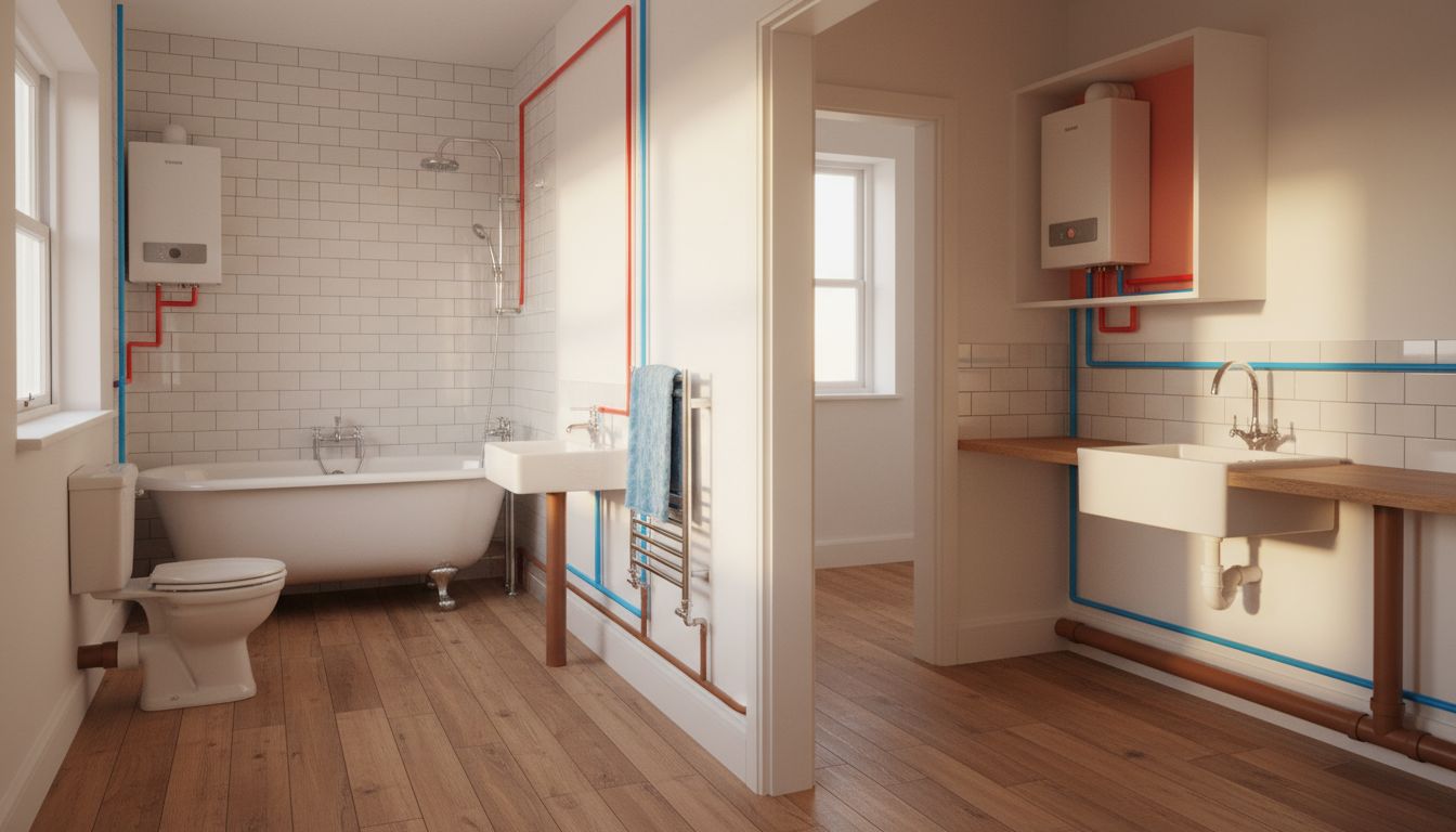
Supply lines and drain lines use different line types or colors to distinguish them. Hot water supply is often shown as a dashed line; cold supply as a solid line. Drain lines show with their diameter noted along the pipe run. Vent lines connect to drain lines and run upward to the roof — these appear on the plumbing floor plan as lines that terminate at the top of the drawing without connecting to a fixture drain.
Reading a Plumbing Floor Plan
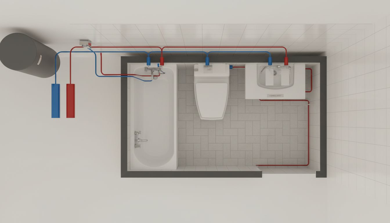
Start at the water meter or main shutoff and trace the cold water supply through the building. It typically runs to the water heater first, then branches to fixtures. Trace the hot water supply from the water heater to each fixture. Note where the lines cross walls — those are the rough-in locations that determine stud bay placement and blocking requirements.
For drain routing, find the main soil stack first. It’s the largest diameter pipe — usually 3 or 4 inches — running vertically through the building. All fixture drains connect to this stack or to branch drains that tie into it. Toilets connect directly. Lavatory sinks, showers, and tubs connect via 1.5 to 2-inch branch drains. The horizontal runs of these drains need sufficient slope — 1/4 inch per foot minimum — which affects where you can place fixtures when you can’t move the stack location.
Drawing Your Own Residential Plumbing Plan
For a permit submission, a residential plumbing plan needs to be drawn to scale — typically 1/4 inch per foot. Start with your architectural floor plan as the base layer. Add fixture locations, then trace the supply and drain routes. Label every pipe with its diameter and material (copper, PEX, PVC, cast iron). Show cleanout locations and any backflow prevention devices. The vent system needs to appear on the drawing, with vent sizes noted.
Software tools like AutoCAD, SketchUp, or dedicated plumbing design software generate accurate scaled drawings. For simple renovations, many homeowners use graph paper and standard plumbing symbols available from the American Society of Plumbing Engineers. Your local building department may have specific requirements for plan format — ask before drawing, not after.
When to Hire a Professional for Plumbing Drawings
For new construction or major additions, a licensed plumbing engineer or master plumber typically stamps the drawings for permit. Simple remodels that stay within existing plumbing locations often don’t require professional drawings, but anything that moves a drain stack, adds a bathroom, or changes the vent system should have professional-grade plumbing blueprints prepared and reviewed before work begins.
Next steps: Before starting any plumbing project, check with your local building department about permit requirements. Many jurisdictions require permit and inspection for any work beyond like-for-like fixture replacement. Getting the plumbing floor plan approved before rough-in work begins prevents having to open walls for inspector access after the fact.